Here's a vid of the engine back in after painting the engine bay and fitting a straight through exhaust. The noise was immense, the muffler will have to go back on I think haha. The jet unit was connected up at this point to check the whole drivetrain. A splitter from the hose is sending coolant to the engine and also to the impellers to help the impellers bed into the ABS wear rings in the jet unit.
Tuesday 3 July 2012
Painting the Engine Bay
With the engine restored and repainted, the engine bay now looked very tired in comparison, so following a good attacking with the degreaser and a wire wheel, it was painted with POR-15 which sets rock hard and provides a waterproof, fuel-proof barrier.

(click image to enlarge)

(click image to enlarge)

(click image to enlarge)

(click image to enlarge)
Thursday 18 August 2011
A Rare Find
Information on the Meteor is pretty much non existent so I was surprised when I stumbled across this advert in Popular Mechanics January 1977. The Meteor was also produced in the US by a company called Link Leisure, presumably under licence from Almarine. They featured a sleeker windshield but were otherwise identical. The information on the engine power is incorrect as I have the Rotax manual for the engine which states 45hp max. The length stated includes the waterjet.

Monday 15 August 2011
Jet Unit - Part 3
A free weekend gave me time to assemble and fit the jet unit with help from a friend. I started by assembling the thrust bearing with a new bearing and new seals (part numbers in earlier post). I then fitted this to the new Duplex Steel shaft having packed the bearing with grease.

Packing thrust bearing with grease before fitting collar and grub screw.

(click image to enlarge)
Here is the collar in place. The collar squashes down into the thrust bearing and provides a watertight seal with the inner seal, but more importantly, stops the shaft being pulled backwards. I drilled a tiny hole in the shaft to locate the collar in position. Tungsten drill bit was no use on the Duplex Steel shaft, ended up using a die grinder. That stuff is tough as hell! No more bent shafts though!

(click image to enlarge)

(click image to enlarge)
I made up a rubber gasket to fit between the two sections of the pump to prevent any gaps. A good use for an old car tyre inner tube! I siliconed this to the mounting face.

(click image to enlarge)
All the jet pump components prior to assembly. Gave the impellers a polish up too, nice and shiny!

(click image to enlarge)
Assembly of the complete unit with the shaft and front impeller in place. You can see the bolts in the shaft to locate the rear impeller. This was previously located with a stainless roll pin.

(click image to enlarge)
Fitting the rear impeller. The stainless collar fits over the end of the shaft and sits in the rear marginally lubricated bearing which is packed with grease. This supports the rear of the shaft.

(click image to enlarge)
Fully assembled unit. Went together a treat and the alignment recess idea made things a whole lot easier. Wasnt cheap to get to this stage but its better than new now and should last many more years.

(click image to enlarge)

(click image to enlarge)

(click image to enlarge)

(click image to enlarge)
Test run in a few weeks. More updates and videos soon.
Tuesday 31 August 2010
Jet Unit - Part 2
After the first test run of the boat, the jet unit was removed and inspected. The rear impeller boss had sheared off the shaft resulting in the rear impeller not turning which could explain the lack in performance towards the end of the day!!! The jet unit had a number of other issues as well such as excessive tip clearance, slightly bent shaft, worn thrust bearing, and bent impeller blades on the rear impeller. The decision to fully recondition the jet unit was therefore straightforward.

The image below shows the shaft assembly for the UA jet unit. The item below is actually my spare unit which I didn't want to use as the rear bearing arrangement is different (bronze bearing) and the impeller blades were in worse condition than the current unit.


The thrust bearing is a simple bronze casting with a sealed ball bearing retained by a large circlip. The bearing is sealed by 2 small oil seals at the rear of the bronze housing and one larger oil seal at the front of the housing. To remove the bearing the large oil seal is removed first. This was being replaced so it didn't matter if I damaged it whilst pulling it out. The circlip can then be removed using circlip pliers. The bearing must be pressed out, and cannot be pushed out by hand. I used the flywheel puller to do this.
Once the thrust bearing is out, the 2 smaller oil seals can be easily removed. All the seals were in bad condition and in need of replacement. I would suggest replacing the oil seals if in doubt as otherwise water and grit can destroy the thrust bearing.


The rear bushing which supports the tail of the shaft is a marginally lubricated cylindrical bushing. The bushing is sealed by a further oil seal. This seal was also replaced. Again this part is available from Nationwide Bearings, Part Number OS352507.

The jet pump housing was known to be in good condition as I had stripped it down before. Nevertheless, it had clearly seen some salt water use as there was some corrosion present. To prolong its life I decided to get the unit powdercoated. While doing this I also stripped down my spare unit and had this sandblasted to get an idea of its condition.


Before powdercoating I had the stator section machined to incorporate an alignment recess (see image below). This was a feature of my spare unit and allowed the partially protruding nozzle section wear ring to slot into the stator section of the jet unit, thus aligning the two sections of the jet unit along the centreline of the shaft. Aligning the two sections is otherwise a matter of trial and error and is the most frustrating part of fitting the jet unit to the boat.
The unit was powdercoated by RPA http://www.bristolmotorcyclepowdercoating.co.uk/index.html who did a great job of the old casting. It had to be heated (gassed) twice to get the trapped gas out of the porous casting before powdercoating. They then applied a primer coat followed by the gloss black final coat as recommended for marine applications. All the bearing surfaces and thread holes were masked off beforehand. The final coating is hard as rock, looks excellent, and should last a long time.

During the powdercoating process, the rear bushing for the shaft got damaged by the heating process. The bearing is of the marginally lubricated type (bronze outer with plastic inner). The plastic bearing surface was melted by the heat so I had to remove the damaged bearing and order a new one (these are available from Ondrives http://www.ondrives.com/index.php Length 25mm, Diameter 25mm, Part Number: PM-2525-DX). The new bearing is pressed into the rear housing (nozzle section).

To improve the performance of the boat, the main repair to the jet unit was to get the shaft straight. This had been straightened before but not enough, resulting in a small eccentricity which prevented the tip clearance between the impeller tips and the wear rings from being the correct dimension. The eccentricity also caused the impellers to contact the wear rings occasionally which could be felt through the boat at certain speeds. I took the dimensions of the original shaft and had a new one made up by Hamble Props http://www.hamblepropellers.com/. The new shaft is made from ultra strong Duplex Stainless Steel and has a slightly increased diameter to further improve strength. The impeller blades were bent in several places and Hamble Props were able to straighten these out to the original shape.
New wear rings were made up from ABS plastic to match the impeller diameter by Plastic Machining Services, Telford http://www.plasticmachiningservices.co.uk/. A tip clearance of 0.2mm was specified. Any further tip clearance reduction was considered to provide insufficient clearance for the natural vibration and flexing of the shaft. The wear rings were pressed into the housings and are held in place through an interference fit.

Rear impeller boss sheared (broken piece visible in stator tunnel)
(click image to enlarge)
The image below shows the shaft assembly for the UA jet unit. The item below is actually my spare unit which I didn't want to use as the rear bearing arrangement is different (bronze bearing) and the impeller blades were in worse condition than the current unit.

Complete shaft assembly (thrust bearing and UJ coupling at front)
(click image to enlarge)
The thrust bearing is removed by removing the sleeve from the front of the shaft. This is located by a small grub screw. The allen key head was rusted out so this was drilled out. The sleeve then slides off. The thrust bearing can then be pulled off with a flywheel puller.
The thrust bearing is removed by removing the sleeve from the front of the shaft. This is located by a small grub screw. The allen key head was rusted out so this was drilled out. The sleeve then slides off. The thrust bearing can then be pulled off with a flywheel puller.

Removal of thrust bearing and housing from shaft using flywheel puller
(click image to enlarge)
The thrust bearing is a simple bronze casting with a sealed ball bearing retained by a large circlip. The bearing is sealed by 2 small oil seals at the rear of the bronze housing and one larger oil seal at the front of the housing. To remove the bearing the large oil seal is removed first. This was being replaced so it didn't matter if I damaged it whilst pulling it out. The circlip can then be removed using circlip pliers. The bearing must be pressed out, and cannot be pushed out by hand. I used the flywheel puller to do this.
Once the thrust bearing is out, the 2 smaller oil seals can be easily removed. All the seals were in bad condition and in need of replacement. I would suggest replacing the oil seals if in doubt as otherwise water and grit can destroy the thrust bearing.

Disassembled thrust bearing housing
(click image to enlarge)
I ordered up new bearings and oil seals (water seals) from Nationwide Bearings http://www.nwideuk.com/.
The part numbers from Nationwide Bearings for the thrust bearing rebuild are:
- Thrust bearing 63022RS
- Small oil seal OS125075025
- Large oil seal OS422507

New thrust bearings and oil seals
(click image to enlarge)
The rear bushing which supports the tail of the shaft is a marginally lubricated cylindrical bushing. The bushing is sealed by a further oil seal. This seal was also replaced. Again this part is available from Nationwide Bearings, Part Number OS352507.

Rear shaft bushing and oil seal (removed)
(click image to enlarge)
The jet pump housing was known to be in good condition as I had stripped it down before. Nevertheless, it had clearly seen some salt water use as there was some corrosion present. To prolong its life I decided to get the unit powdercoated. While doing this I also stripped down my spare unit and had this sandblasted to get an idea of its condition.

Jet unit (and spare unit) prior to blasting
(click image to enlarge)

Jet unit (and spare unit to left) after blasting
(click image to enlarge)
Before powdercoating I had the stator section machined to incorporate an alignment recess (see image below). This was a feature of my spare unit and allowed the partially protruding nozzle section wear ring to slot into the stator section of the jet unit, thus aligning the two sections of the jet unit along the centreline of the shaft. Aligning the two sections is otherwise a matter of trial and error and is the most frustrating part of fitting the jet unit to the boat.
The unit was powdercoated by RPA http://www.bristolmotorcyclepowdercoating.co.uk/index.html who did a great job of the old casting. It had to be heated (gassed) twice to get the trapped gas out of the porous casting before powdercoating. They then applied a primer coat followed by the gloss black final coat as recommended for marine applications. All the bearing surfaces and thread holes were masked off beforehand. The final coating is hard as rock, looks excellent, and should last a long time.

Jet unit after powdercoating. Alignment recess on stator section visible (bare aluminium).
(click image to enlarge)
During the powdercoating process, the rear bushing for the shaft got damaged by the heating process. The bearing is of the marginally lubricated type (bronze outer with plastic inner). The plastic bearing surface was melted by the heat so I had to remove the damaged bearing and order a new one (these are available from Ondrives http://www.ondrives.com/index.php Length 25mm, Diameter 25mm, Part Number: PM-2525-DX). The new bearing is pressed into the rear housing (nozzle section).

Damaged rear bushing. Replacement bushing must be pressed in.
(click image to enlarge)
To improve the performance of the boat, the main repair to the jet unit was to get the shaft straight. This had been straightened before but not enough, resulting in a small eccentricity which prevented the tip clearance between the impeller tips and the wear rings from being the correct dimension. The eccentricity also caused the impellers to contact the wear rings occasionally which could be felt through the boat at certain speeds. I took the dimensions of the original shaft and had a new one made up by Hamble Props http://www.hamblepropellers.com/. The new shaft is made from ultra strong Duplex Stainless Steel and has a slightly increased diameter to further improve strength. The impeller blades were bent in several places and Hamble Props were able to straighten these out to the original shape.
New wear rings were made up from ABS plastic to match the impeller diameter by Plastic Machining Services, Telford http://www.plasticmachiningservices.co.uk/. A tip clearance of 0.2mm was specified. Any further tip clearance reduction was considered to provide insufficient clearance for the natural vibration and flexing of the shaft. The wear rings were pressed into the housings and are held in place through an interference fit.
Wednesday 24 February 2010
Launch Day 2
More photos from first run. I didn't fiddle with the engine settings so can go quite a bit leaner on the fuel mix and also dial in some more advance timing on the MSD ignition. I ran a conservative map at 20degrees advance ignition timing out of an estimated maximum 25 degrees. Standard igntion timing is fixed at 18degrees +/- 2 degrees.

Aim for the middle of the lake!
(click photo to enlarge)

Britannia rules the waves!! Red ensign from my Dads old Fletcher speedboat.
(click photo to enlarge)

(click photo to enlarge)

(click photo to enlarge)

(click photo to enlarge)

Boating heaven!
(click photo to enlarge)

(click photo to enlarge)

(click photo to enlarge)

(click photo to enlarge)

(click photo to enlarge)
Saturday 13 February 2010
Launch Day
The boat finally got wet at the end of October 2009. I was very lucky to be able to use a local lake to test the boat. The lauch went well and no leaks were found. After the naming ceremony (where she was named "Soap Dish") it was time to start the engine a go for a spin. The engine started on the button and everything seemed in order. Once she was warmed up, i took her out and tested the steering and then after tootling around for a bit, tried to get her up on the plane. It quickly became appartent that the jet unit had some major problems as the jet would slip as more throttle was applied. A quick burst of throttle only produced a load of bubbles, but did not result in any decent acceleration. To get the thing on the plane, i had to feed the throttle in gently, but there remained the sensantion that the jet unit was not running well and could be likened to the feeling of the clutch slipping in a car. The problem was put down to the tip clearance around the impellers (the distance between the impeller tips and the wear rings). After the run the jet unit was disassembled and the tip clearance was found to be way too big (about 2mm). The recommended tip clearance for jet units is about 0.2mm. I was aware the tip clearance was big but had not expected such a drop in performance and had deliberately left the tip clearance as it was to account for the small eccentricity in the shaft. The jet unit has now been removed and is undergoing a full rebuild with a new Duplex Stainless Steel shaft and new wear rings sized to give the correct tip clearance.
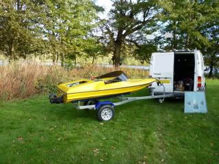

At the top of the slipway ready for launch!
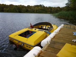
In the water again, after years in the shed
Subscribe to:
Posts (Atom)